When designing an earth grid for a substation or another high voltage installation, it is generally easy to produce a compliant design for touch step voltages both within and immediately around the installation. To mitigate Touch voltages, they are buried with grading conductors or surface treatments. This includes things such as crushed rock or asphalt, and step voltages. These are mitigated by controlling the voltage profiles at the edges of the earth grid.
Many designers will reach this point and consider the design compliant and fit for implementation. Doing so, however, does not consider what often represents the most significant earthing hazards for the installation.
Equipment and structures around the earthing system can be remotely earthed. They also can be bonded to the Low Voltage Multiple Earthed Neutral (MEN) earthing system. This may result in high touch voltages to the equipment and to the structures during an earth fault at the substation.
Furthermore, this equipment is also usually available for access by the general public. In opposition, equipment within the substation is only accessed by qualified personnel. Overall, this results in a higher risk profile which is often overlooked in earthing system designs.
Consider, for example, a high voltage underground to overhead (UGOH) termination pole earth grid.
A typical earthing design may involve designing an earth grid with a resistance below 10ohms for lightning. This may include a switching surge dissipation as the extent of the design.
An earthing design, such as this, has not considered the earth fault hazard scenario that has been introduced to the area. It also has not considered the effect of this earth grid on services or the infrastructure surrounding the UGOH pole.
A more thorough earthing design would involve performing a detailed services search. This establishes the buried services in the area and site inspections to determine infrastructure.
This can be affected by several things including the earthing design and a review of aerial photography of the area. The aerial photography is to build a complete picture of the area. Introducing an earthing system will also affect existing assets in the area.
After combining all this information, with the correct tools, a designer can produce an accurate 3D representation of the area. The designer produces this in an earthing design software package.
This 3D representation is then utilised to determine the effects of the earthing system on the nearby infrastructure.
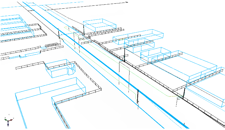
The image below shows a recent PowerEarth study. The study, as shown, is a high voltage UGOH earthing system design.
The image includes buried services as well as above-ground structures. Buried services include water distribution mains, water street mains, gas mains, telecommunications assets. Above-ground structures include buildings, small structures and fences.

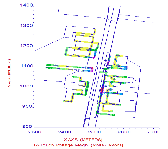
A detailed earthing system design can consider the residual hazards of surrounding assets. This is a result of the introduction of an earth fault hazard scenario. The hazards can then be mitigated to produce a compliant earthing system design. In our example, we use the touch voltage plots (such as in the image below) to optimise the UGOH earthing system design. This reduces touch voltages to its surrounding infrastructure so far as is reasonably practical.

When performing earthing system designs, we must think big. We must consider how the earthing system can affect the assets around them. We then must consider the hazards introduced as a result of this. Every effort must be made to reduce these hazards to ensure a safe system. Contact PowerEarth today if you request earthing services or more information.

